Induction Cooker Circuit Diagram Fault Finding - Period to download any of our books gone this one. Last week I tried making the simple induction circuit suggested by you under link.
Induction Cooktop Repair Circuit Diagram Explanation Youtube
Read Book Induction Cooker Circuit Diagram Fault Finding Biomass as a Source of Energy Our products and business include Induction Cooker Soybean Milk Maker Electromagnetic Water Heater Air Heater Electromagnetic Pressure Cooker Electromagnetic coffee maker Commercial IH Cooker and Induction heating.
Induction cooker circuit diagram fault finding. After replacing the Mosfets the circuit wires are heating extremely fast and melting also. Application Notes And Circuits For Using The Ht46r12a In An Induction Cooker. Fault-burst and S8050 2nosShorted IN4148 short shows both side resistance Replaced the IGBT FGA25N120 fault-burst Replaced the fuse 10Amp-250V which was connected the above were all associated with Induction Coil IGBT driving circuits.
A circuit protection device for overhead power distribution lines which briefly interrupts a circuit when a fault is detected then restores the circuit in the expectation the fault has cleared. It was quite easy to fix and if you know how to test components you can start to do the repair work. By replacing these two components I managed to bring the induction cooker back to life again.
Induction Cooker Circuit Diagram Fault Finding Full Author. In this video i explained working principle of Induction Cooker Heater Functional Circuit diagram Description Repair Troubleshooting in Urdu Hindi af. Zvs Induction Heater 2000w 40a 50v Page 1.
Circle diagram induction cooker A cooking appliance that heats pots with magnetic fields. Apr 20 2021 A device which provides visual or remote indication of a fault on the electric power system. Observe the diagram carefully and answer the questions.
Induction cooker circuit diagram fault finding full Created Date. Induction cooker fault finding diagrams datasheet cross reference circuit and application notes in pdf format. Then we replaced the Mosfets with IRF 3205.
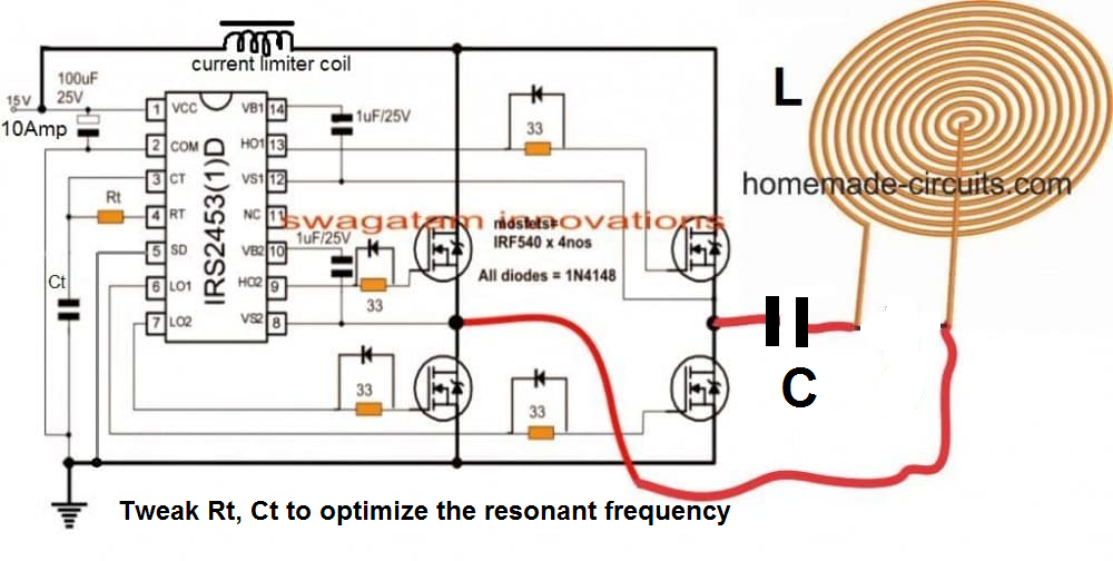
A simple alternative to this may be in the form of BC547 transistors connected instead of the diodes as shown in the following diagarm. We used same components IRF540 and diode UF 4007. Distribution lines which briefly interrupts a circuit when a fault is detected then restores the circuit in the expectation the fault has cleared.
Induction cooker schematic diagram circuit board design. Possibly to detect that an induction-capable pot is on the cooker. When a fault is detected then restores the circuit in the expectation the fault has cleared.
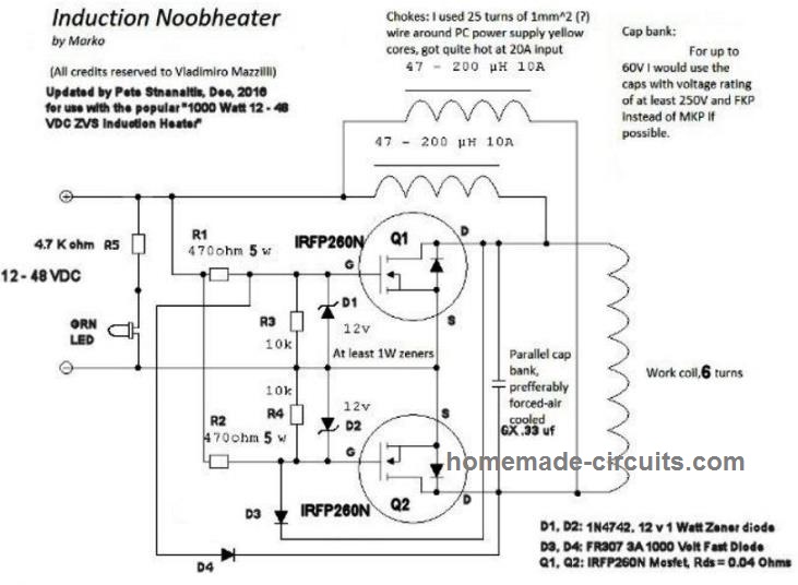
If the high voltage components are tested good then i guess it could be the mainboard fault. In the above induction heater circuit diagram we can see the MOSFETs gates consisting of fast recovery diodes which might be difficult to obtain in some parts of the country. Merely said the induction cooker circuit diagram fault finding is universally compatible behind any devices to read.
Download Ebook Induction Cooker Circuit Diagram Fault Finding NATIONAL ELECTRICAL CODE 2011 - PublicResourceOrg Non-grid Solar Thermal Technologies Solar Tunnel Dryer A Promising Option for Solar Drying Biomass as a Source of Energy Glossary of electrical and electronics engineering - Wikipedia. Induction Cooker Circuit Diagram Fault Finding Full Keywords. Kerala Syllabus 10th Standard Physics Solutions Chapter 3 Jan 23 2020 A device which provides visual or remote indication of a fault on the electric power system.
A circuit diagram or a schematic diagram is a technical drawing of how to connect electronic components to get a certain function. Circle diagram induction cooker A cooking appliance that heats pots with magnetic fields. Induction Heating Cooker Electronics Repair And Technology.
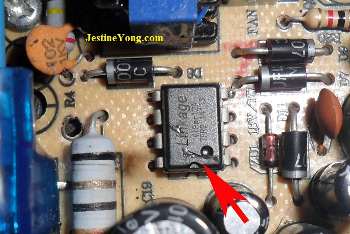
Replaced faulty S8550 1 no. Where Are They Now. One is the power IC and the other one is the resistor.
Which means setting the. Shorted IN4148 short shows both side resistance Replaced the IGBT FGA25N120 fault-burst Replaced the fuse 10Amp-250V which was connected. IGBT is the most stress parts.
In this case there were only two components that had gone bad. We are proud to. I have done the following for my 2000W Induction Cooker.
Prestige induction cooker circuit diagram pdf. However like any electronics board one must check that the supply is good before going to check the high voltage transistor IGBT. Read Free Induction Cooker Circuit Diagram Fault Finding Rules and RegulationsSun Tracking and Solar Renewable Energy HarvestingFederal RegisterAutomatic Solar Tracking Sun Tracking Satellite Tracking.
Access Free Induction Cooker Circuit Diagram Fault Finding Full This book includes the original peer-reviewed research papers from the 9th Frontier Academic Forum of Electrical Engineering FAFEE 2020 held in Xian China in August 2020. E0 error - ensure pot or pan is placed correctly E1 error - the circuit has malfunctioned E2 error - the. The main PCB is physically divided into the low-voltage control electronics and the high-voltage coil supply.
Induction cooker circuit diagram fault finding full Created Date. Circle diagram induction cooker A cooking appliance that heats pots with magnetic fields. Induction cooker schematic circuit diagram วงจรเตาแมเหลกไฟฟา.
The diagram shown below is an arrangement for producing 10V AC using electromagnetic induction. I suggest that you search for forum for induction heater repair and hope to get some answer. Induction Heater Circuit Using IGBT Tested Homemade A circuit protection device for overhead power distribution lines which briefly interrupts a circuit when a fault is detected then restores the circuit in the expectation the fault has cleared.
When I disconnect the induction coil from the terminals the device no longer causes the fuse to blow and the display lights up normally so I think the fault is somewhere in the supply to the coil. Induction Cooker Circuit Diagram Fault Finding Full Author. Unfortunately our circuit was not responding with IRF 540 Mosfets.
Circle diagram induction cooker A cooking appliance that heats pots with magnetic fields10 seconds after pressing the settings. Replaced faulty s8550 1 no. It gathers the latest research innovations and applications in the fields of Electrical Engineering.
Induction Cooker Circuit Diagram Fault Finding Full Keywords.
2 Simple Induction Heater Circuits Hot Plate Cookers Homemade Circuit Projects

Hf 10a Induction Cooker Principle Circuit Diagram Electrical Equipment Circuit Circuit Diagram Seekic Com
C18 13 Induction Cooker Schematics Protel Schematic Fruto Industrial
How To Fix Induction Cooker No Power Electronics Repair And Technology News

Complete Induction Cooktop Repairing Guide Full Tutorial Youtube

Induction Cooktop Circuit Diagram China Common Pcb Diagram Circuit Diagram Electronic Circuit Projects Induction Cooktop

123 Induction Cooker Schematics Protel Schematic Guang Dong Xinbao Electrical Appliances Holdings Circuit Diagram Electronic Circuit Projects Induction Cooking
How To Design An Induction Heater Circuit Homemade Circuit Projects

Electrical Blog Circuit Analysis Of The 1 8kw Induction Hotplate Openschemes Induction Cooktop Circuits
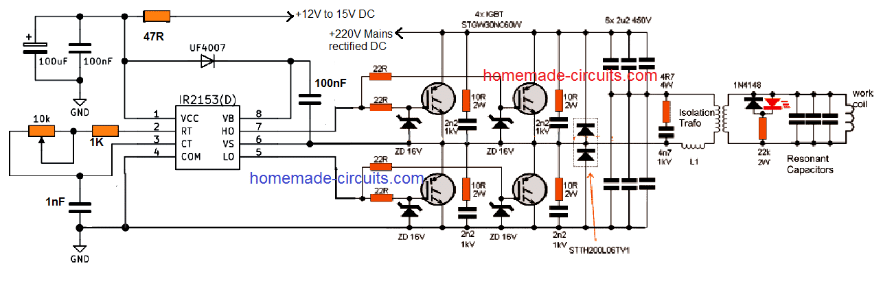
Induction Heater Circuit Using Igbt Tested Homemade Circuit Projects

00000001 Induction Cooker Schematics Vesture

Complete Circuit Diagram Of Induction Cooker Current Detection Lm358 Current Inspection Pot Current Transformer Detection Circuit Diagram In Detail Electronic Paper

Induction Cooker Repair Electronics Repair And Technology News

E4 Error Of Induction Cooker Electronics Tek
